Mesh Formats
Summary
Description of the various mesh formats that can be used with GLVis.
Details
GLVis supports a number of mesh formats, including:
- The MFEM mesh v1.0 format, which can describe very general meshes based on any finite element grid function supported by MFEM, including NURBS meshes.
- The VTK unstructured mesh format, for triangular, quadrilateral, tetrahedral and hexahedral meshes. See the curvilinear VTK tutorial for more details. Some examples of VTK meshes can be found in MFEM's data directory.
- The Gmsh ASCII and binary formats for 2D and 3D meshes.
- The CUBIT meshes through the Genesis (NetCDF) binary format.
- The NETGEN triangular and tetrahedral mesh formats.
- The TrueGrid hexahedral mesh format.
MFEM mesh v1.0
This is the default format in GLVis. It can be used to describe simple (triangular, quadrilateral, tetrahedral and hexahedral meshes with straight edges) or complicated (curvilinear and more general) meshes.
Straight meshes
In the simple case of a mesh with straight edges the format looks as follows
MFEM mesh v1.0

# Space dimension: 2 or 3
dimension
<dimension>

# Mesh elements, e.g. tetrahedrons (4)
elements
<number of elements>
<element attribute> <geometry type> <vertex index 1> ... <vertex index m>
...

# Mesh faces/edges on the boundary, e.g. triangles (2)
boundary
<number of boundary elements>
<boundary element attribute> <geometry type> <vertex index 1> ... <vertex index m>
...

# Vertex coordinates
vertices
<number of vertices>
<vdim>
<coordinate 1> ... <coordinate <vdim>>
...
Lines starting with "#" denote comments. The supported geometry types are:
- POINT = 0
- SEGMENT = 1
- TRIANGLE = 2
- SQUARE = 3
- TETRAHEDRON = 4
- CUBE = 5
see the comments in this source file for more details.
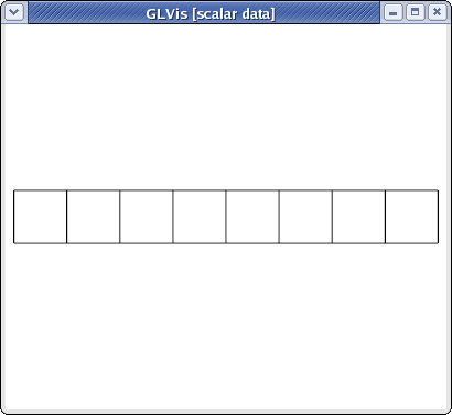
For example, the beam-quad.mesh file from MFEM looks like this:
MFEM mesh v1.0

dimension
2

elements
8
1 3 0 1 10 9
1 3 1 2 11 10
1 3 2 3 12 11
1 3 3 4 13 12
2 3 4 5 14 13
2 3 5 6 15 14
2 3 6 7 16 15
2 3 7 8 17 16

boundary
18
3 1 1 0
3 1 2 1
3 1 3 2
3 1 4 3
3 1 5 4
3 1 6 5
3 1 7 6
3 1 8 7
3 1 9 10
3 1 10 11
3 1 11 12
3 1 12 13
3 1 13 14
3 1 14 15
3 1 15 16
3 1 16 17
1 1 0 9
2 1 17 8

vertices
18
2
0 0
1 0
2 0
3 0
4 0
5 0
6 0
7 0
8 0
0 1
1 1
2 1
3 1
4 1
5 1
6 1
7 1
8 1
which corresponds to the mesh

visualized with
glvis -m beam-quad.mesh -k "Ame****"
Curvilinear and more general meshes
The MFEM mesh v1.0 format also support the general description of meshes based on a vector finite element grid function with degrees of freedom in the "nodes" of the mesh:
MFEM mesh v1.0

# Space dimension: 2 or 3
dimension
<dimension>

# Mesh elements, e.g. tetrahedrons (4)
elements
<number of elements>
<element attribute> <geometry type> <vertex index 1> ... <vertex index m>
...

# Mesh faces/edges on the boundary, e.g. triangles (2)
boundary
<number of boundary elements>
<boundary element attribute> <geometry type> <vertex index 1> ... <vertex index m>
...

# Number of vertices (no coordinates)
vertices
<number of vertices>

# Mesh nodes as degrees of freedom of a finite element grid function
nodes
FiniteElementSpace
FiniteElementCollection: <finite element collection>
VDim: <dimension>
Ordering: 0
<x-coordinate degrees of freedom>
...
<y-coordinate degrees of freedom>
...
<z-coordinate degrees of freedom>
...
Some possible finite element collection choices are: Linear, Quadratic and Cubic corresponding to curvilinear P1/Q1, P2/Q2 and P3/Q3 meshes. The algorithm for the numbering of the degrees of freedom can be found in MFEM's source code.
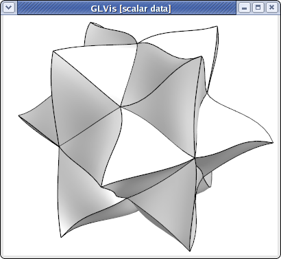
For example, the escher-p3.mesh from MFEM's data directory describes a tetrahedral mesh with nodes given by a P3 vector Lagrangian finite element function. Visualizing this mesh with
glvis -m escher-p3.mesh -k "Aaaaoooooooooo**************tt"
we get:

NURBS meshes
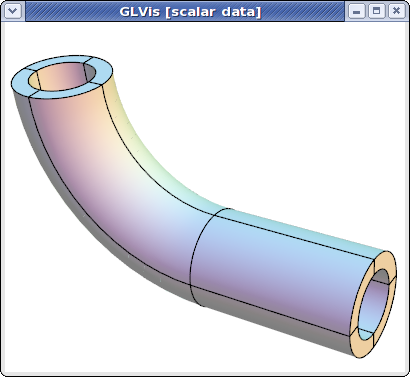
NURBS meshes and functions are fully supported in GLVis. For example,
glvis -m pipe-nurbs.mesh
produces after some refinement (key "o") and mouse manipulations

More details about the NURBS mesh format can be found in the separate NURBS tutorial.